


close
Choose Your Site
Global
Social Media


Views: 0 Author: Site Editor Publish Time: 2026-08-14 Origin: Site


Utility infrastructure reliability hinges entirely on the structural and electrical integrity of its base components. A single point of failure in overhead distribution, transmission, or telecom systems can result in catastrophic grid downtime. Standard off-the-shelf components frequently fail to meet the unique load requirements, extreme environmental conditions, or legacy infrastructure compatibility needed for specialized utility projects. Procurement and engineering teams face the challenge of sourcing custom components without compromising on compliance or extending lead times.
Mitigating risk requires a deep understanding of how custom utility components are fabricated. Evaluating a manufacturer’s specific engineering, machining, and testing processes is the only reliable framework for shortlisting a vendor. Relying on superficial specifications often leads to premature field failures. You must verify the metallurgical properties, dimensional tolerances, and environmental resilience of every piece of hardware before installation.
Material selection dictates lifecycle: The choice between forged steel, cast iron, and specific aluminum alloys directly impacts the tensile strength and corrosion resistance of transmission line hardware.
Precision in machining is non-negotiable: Core fabrication steps—such as preparing, shearing, punching, drilling, and filing—must be tightly controlled to ensure batch-to-batch consistency in custom utility pole fittings.
Finishing determines environmental resilience: Hot-dip galvanizing and advanced polymer coatings are critical evaluation dimensions for preventing premature degradation in overhead distribution lines.
Verified compliance mitigates liability: A credible manufacturing partner must provide transparent, documented testing for mechanical load limits and electrical insulation to meet ANSI, IEC, and IEEE standards.
Table of Contents
Off-the-shelf utility components serve standard grid layouts effectively. However, operational realities often dictate deviations from standard designs. High-tension river crossings introduce extreme mechanical stress that standard dead-ends cannot safely support. Coastal environments expose infrastructure to heavy salinity, accelerating corrosion beyond the protective limits of standard galvanization. Furthermore, retrofitting non-standard legacy poles or integrating heavy joint-use telecom equipment requires mounting brackets and crossarm configurations that simply do not exist in standard catalogs.
Attempting to modify standard parts in the field introduces severe liability and compromises structural integrity. Field crews drilling new holes into galvanized steel brackets immediately destroy the protective zinc coating, guaranteeing rapid rust formation. Bending standard clamps to fit oversized conductors creates micro-fractures in the metal grain structure. Custom engineering becomes the only viable path forward to maintain system integrity.
Defining success in custom procurement requires strict adherence to specific operational criteria. You need exact dimensional tolerances to ensure seamless field installation. A bracket that is off by a fraction of an inch will delay a multi-person crew and require expensive rework. You require verified load-bearing capacities documented through destructive testing. Predictable lead times are necessary to keep large-scale grid expansion or repair projects on schedule. Finally, strict adherence to utility-specific compliance mandates ensures that custom hardware does not become a regulatory liability.
Procuring custom components shifts the focus from unit cost to operational lifecycle. A custom-engineered suspension clamp that perfectly matches a specific conductor diameter prevents conductor fatigue and abrasion. This extends the lifespan of the entire span, reducing maintenance truck rolls and preventing unplanned outages.
High-Tension Spans: Standard dead-ends fail under the extreme mechanical stress of long river or valley crossings.
Coastal Salinity: Standard galvanization degrades rapidly in heavy salt-spray environments, requiring custom polymer coatings or specialized aluminum alloys.
Legacy Infrastructure: Upgrading 50-year-old non-standard poles requires custom mounting brackets to integrate modern transformers and switchgear.
Joint-Use Overload: Adding heavy telecom fiber lines to existing distribution poles demands custom crossarms and heavy-duty guying hardware to handle the increased wind load.

The overhead utility environment requires a diverse array of specialized components. Each serves a distinct mechanical or electrical function. Crossarms provide the primary structural support for conductors and insulators. Drop out fuse cutout switchgear protects transformers and lines from overcurrent faults. Earthing and grounding materials safely dissipate fault currents into the earth. Ties, grips, splices, and dead-ends manage conductor tension and secure lines to insulators. Line guards, armor rods, and lashing rods protect conductors from vibration fatigue and abrasion at support points.
Sourcing reliable Power Line Hardware requires matching the specific component to the appropriate metallurgical profile. Carbon steel is heavily utilized for structural components requiring high tensile strength, such as heavy-duty crossarm braces and structural bolts. Grades like ASTM A36 or A572 provide the necessary yield strength to support heavy transformers and multiple conductor spans. Ductile iron offers excellent castability combined with high yield strength, making it ideal for complex shapes like suspension clamps and clevises. Its nodular graphite structure prevents the crack propagation common in standard gray iron, allowing the fitting to deform slightly under extreme stress rather than shattering.
Malleable iron provides a balance of strength and ductility. Manufacturers often use it for smaller fittings that must withstand impact without fracturing during installation or severe weather events. The annealing process gives malleable iron its unique properties, making it a staple in distribution hardware.
Weight reduction is a primary concern for transmission towers. Aluminum alloys are extensively used for transmission line hardware, including corona rings and specific suspension clamps. Alloys like 6061-T6 or 356.0 provide a high strength-to-weight ratio and natural corrosion resistance. For insulation, the industry has largely transitioned from traditional porcelain to fiberglass and polymer composites. These materials offer superior hydrophobicity, lighter weight, and resistance to vandalism, making them ideal for custom insulator profiles.
Metallurgical Profiles for Utility Components
Material Type | Common Grades | Primary Characteristics | Typical Field Applications |
|---|---|---|---|
Carbon Steel | ASTM A36, A572 | High tensile strength, rigid, requires heavy galvanization. | Crossarm braces, structural bolts, heavy-duty mounting brackets. |
Ductile Iron | ASTM A536 | High yield strength, resists crack propagation, excellent castability. | Suspension clamps, clevises, socket eyes, heavy dead-end bodies. |
Malleable Iron | ASTM A47 | Good ductility, withstands impact, moderate strength. | Guy strain insulators, secondary racks, smaller interlocking fittings. |
Aluminum Alloys | 6061-T6, 356.0 | High strength-to-weight ratio, natural corrosion resistance, non-magnetic. | Corona rings, transmission suspension clamps, vibration dampers. |
Transforming raw metal into field-ready utility hardware is a multi-stage industrial process. It begins in the engineering department. Engineers utilize Computer-Aided Design (CAD) to model the custom component based on utility specifications. Finite Element Analysis (FEA) simulates mechanical stress, wind shear, and ice loading to identify potential failure points before any metal is cut. FEA software applies virtual loads to the 3D model, highlighting stress concentrations in red. Engineers then thicken these specific areas or adjust the geometry to distribute the load evenly. Once the design is validated, custom tooling and dies are machined.
Forming the metal dictates the component's internal grain structure and ultimate strength. Drop forging is utilized for high-stress components like heavy-duty dead-ends and suspension clamps. In this process, heated metal billets are forced into custom dies under extreme pressure from a drop hammer. This aligns the metal's grain structure with the shape of the part, maximizing tensile strength and fatigue resistance. A forged steel eye nut will always outperform a cast equivalent in pure tensile loading.
Conversely, casting is used for complex geometries that cannot be forged. Sand casting and investment casting allow for intricate internal cavities and complex external shapes. Molten metal is poured into a mold cavity and allowed to solidify. While cast parts generally have lower tensile strength than forged parts, utilizing ductile iron mitigates this difference for many applications. The casting process allows for the integration of multiple features—like interlocking hinges and bolt channels—into a single solid piece, reducing assembly time.
Secondary fabrication brings the formed metal into exact dimensional tolerance. Automated CNC machining centers perform shearing, punching, and drilling operations. CNC technology ensures that bolt holes align perfectly across thousands of units, preventing installation delays in the field. Heavy-tonnage presses shear and punch steel plates for crossarm brackets with repeatable precision. Machining tolerances for utility hardware typically range from +/- 0.010 inches for standard brackets to +/- 0.002 inches for interlocking switchgear components.
Filing and surface preparation represent a mandatory manufacturing stage. Machining leaves sharp edges and burrs. If left intact, these burrs can damage conductor insulation during installation or create weak points in the protective zinc coating. Mechanical deburring using vibratory tumblers and manual filing ensure all surfaces are smooth and safe for handling. Proper surface preparation also involves shot blasting to remove casting sand and scale, providing a clean substrate for the final coating.
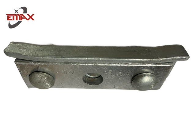
The final manufacturing step is hot-dip galvanizing (HDG). This is not a simple dip process; it is a strict metallurgical bonding procedure. Components are first submerged in a caustic solution to remove dirt and oil. They are then rinsed and pickled in a bath of hydrochloric or sulfuric acid to strip away mill scale and rust. After another rinse, the parts are dipped in a flux solution to prevent oxidation before entering the zinc bath. The parts are submerged in molten zinc at approximately 830°F (443°C). The zinc reacts with the steel to form a series of tightly bonded zinc-iron alloy layers (Gamma, Delta, Zeta) topped with a layer of pure zinc (Eta). This metallurgical bond provides superior abrasion resistance and cathodic protection against rust. Zinc coating thickness is strictly measured using magnetic thickness gauges to ensure compliance with ASTM A153 standards.
Manufacturing precision means nothing without documented verification. Quality assurance protocols must directly connect specific testing dimensions to operational reliability. You cannot assume a custom part will perform based solely on its material composition. Rigorous physical testing is required to validate the engineering models.
Mechanical load testing pushes hardware to its breaking point. Manufacturers conduct destructive testing on sample batches using a Universal Testing Machine (UTM). The UTM applies increasing tension to the component until it fractures, recording the exact yield point and ultimate tensile strength via a calibrated load cell. This verifies that the hardware can withstand severe ice loads and line tension. Fatigue testing simulates decades of wind-induced vibration. Components like armor rods and suspension clamps are subjected to millions of cyclic loads to ensure they will not fail under continuous aeolian vibration. Proof load testing applies a predetermined safe working load to verify that the component does not permanently deform under operational stress.
Electrical and thermal testing are mandatory for insulators, switchgear, and conductive hardware. Arc tracking tests verify that polymer insulators resist surface degradation when exposed to high voltage and moisture. The insulator is subjected to a continuous voltage while a saline solution is dripped across its surface, simulating coastal fog or heavy pollution. Thermal cycling exposes hardware to extreme temperature fluctuations in environmental chambers. This ensures that dissimilar metals, such as aluminum conductors clamped in galvanized steel, do not loosen due to differing rates of thermal expansion and contraction.
Regulatory compliance acts as the final gatekeeper. A credible manufacturer must provide documented proof of compliance with global standards. This includes ANSI (American National Standards Institute) for dimensional and performance criteria, IEC (International Electrotechnical Commission) for electrical ratings, IEEE (Institute of Electrical and Electronics Engineers) for specific application guidelines, and ASTM (American Society for Testing and Materials) for galvanization and material properties. Without these certifications, custom hardware presents a massive liability risk to the utility operator.
Standard Compliance and Testing Protocols
Testing Category | Primary Protocol / Standard | Operational Outcome |
|---|---|---|
Mechanical Strength | Destructive Tensile Testing (UTM) | Verifies ultimate load capacity against ice and wind shear. |
Corrosion Resistance | ASTM A153 / ASTM B117 (Salt Spray) | Ensures adequate zinc coating thickness for long-term rust prevention. |
Electrical Insulation | IEC 61109 (Polymer Insulators) | Validates resistance to arc tracking and surface degradation. |
Dimensional Accuracy | First Article Inspection (FAI) | Guarantees seamless field installation and compatibility. |
Vibration Fatigue | Cyclic Load Testing | Prevents premature failure of clamps and rods due to wind vibration. |
Selecting a manufacturing partner requires evaluating factors far beyond the initial unit cost. The cheapest component becomes the most expensive if it fails during a winter storm, causing a localized blackout and requiring emergency crew deployment. You must assess the vendor's structural capacity to deliver engineered solutions consistently over the lifespan of your grid modernization project.
Sourcing from a direct manufacturer offers significant strategic advantages over purchasing through a distributor. Direct manufacturers provide immediate control over the customization process. Engineering changes can be implemented rapidly, and quality assurance oversight is direct. If a prototype fails a load test, the manufacturer's engineers can adjust the CAD model and machine a new die within days. Distributors offer bundled inventory and potentially faster shipping for standard parts, but they lack the agility to modify tooling or adjust metallurgical profiles for custom requests. You are entirely dependent on their upstream supply chain.
Industry tenure serves as a reliable indicator of capability. A manufacturer with decades of specialized experience in overhead distribution and telecom hardware possesses deep tooling expertise. They understand the nuances of die wear, material shrinkage during casting, and the specific tolerances required for utility applications. This track record generally translates to supply chain stability and predictable output. Ask potential vendors for case studies detailing their work on similar custom utility projects.
Production capacity must align with your project timelines. A facility may have excellent engineering capabilities but lack the heavy-tonnage presses or large galvanizing baths needed to produce high volumes quickly. Discuss tooling capacity upfront. Understand their lead times for creating custom dies versus their lead times for full-scale production runs. A vendor that outsources their galvanizing will have longer lead times and less control over the final coating quality than a vendor with an in-house HDG line.
The decision between domestic and overseas sourcing involves weighing cost against risk. Overseas manufacturing often provides lower unit costs due to reduced labor and facility overhead. However, this introduces extended shipping times, potential tariff fluctuations, and challenges in direct QA oversight. Domestic sourcing offers faster communication, easier facility audits, and shorter transit times, though typically at a higher initial production cost. The choice depends on project urgency, budget constraints, and internal QA resources available for factory audits.
Custom manufacturing carries inherent risks that must be managed proactively. Raw material volatility is a primary concern. The global markets for steel, aluminum, and zinc fluctuate constantly based on geopolitical events and supply chain disruptions. A sudden spike in raw material costs can derail a project budget before the first part is even cast. Mitigate this risk by structuring contracts that lock in material pricing at the time of order. Alternatively, work with manufacturers who have the capital to secure raw material reserves for large, long-term projects, insulating your procurement budget from market shocks.
Tooling degradation poses a significant risk to batch consistency. Custom dies wear down over thousands of forging or stamping cycles. The friction of hot metal against the die face slowly alters the cavity dimensions. As the die wears, dimensional tolerances drift. A component produced in the first batch may fit perfectly, while a component from the tenth batch may fail field installation due to oversized bolt channels or misaligned interlocking tabs. Mitigate this by auditing the manufacturer's tooling maintenance schedule. Require a First Article Inspection (FAI) report for every new production run. The FAI verifies that the tooling is still producing parts within the exact engineered tolerances before full-scale manufacturing resumes. If the FAI shows tolerance drift, the manufacturer must re-machine or replace the die.
Submit detailed CAD drawings to the manufacturer's engineering team for a comprehensive manufacturability review and stress analysis.
Request a First Article prototype quote to physically verify dimensional accuracy, metallurgical properties, and finish quality.
Establish a clear Service Level Agreement (SLA) that strictly defines acceptable defect rates, delivery timelines, and mandatory testing documentation.
Schedule a facility audit to inspect the manufacturer's in-house tooling capabilities, CNC machining centers, and hot-dip galvanizing lines.
Founded in 1993, Hangzhou Emax Industrial Co., Ltd brings decades of manufacturing experience to industrial hardware production, with capabilities covering pole line hardware, grounding hardware, stamping, sheet metal fabrication, and other custom components. Supported by an 11,000-square-meter facility and integrated engineering and production capabilities, Emax works with customers to develop reliable hardware solutions for diverse utility and industrial applications.
A: Carbon steel is used for high-strength structural components like crossarm braces. Ductile iron is utilized for complex cast shapes like suspension clamps due to its high yield strength and resistance to cracking. Aluminum alloys are chosen for transmission hardware where weight reduction and natural corrosion resistance are required.
A: This category encompasses a wide range of structural and functional fittings. Common components include crossarms, insulators, ties, suspension clamps, dead-end grips, splices, line guards, armor rods, and various earthing and grounding materials used in overhead distribution.
A: The primary protection method is hot-dip galvanizing (HDG). Components are cleaned, pickled in acid, and submerged in molten zinc. This creates a metallurgical bond that provides thick, durable rust protection. Meticulous surface preparation ensures the zinc coating adheres uniformly without weak spots.
A: Forging involves pressing heated metal into dies under extreme pressure, aligning the grain structure for exceptionally high tensile strength. Casting involves pouring molten metal into molds, allowing for highly complex geometries and internal cavities that cannot be achieved through forging.
A: Timelines vary based on complexity. Initial engineering, CAD modeling, and custom die creation typically take 3 to 6 weeks. Prototyping and First Article Inspection add another 2 to 4 weeks. Full-scale production, galvanizing, and QA testing generally require an additional 4 to 8 weeks.
A: A reliable manufacturer must adhere to strict global standards. Look for ISO 9001 certification for quality management. Products should meet ANSI for dimensional tolerances, IEEE for application guidelines, IEC for electrical performance, and ASTM A153 for hot-dip galvanization thickness.
A: Modifying standard hardware in the field is highly dangerous. Drilling new holes or bending brackets compromises the engineered load capacity and destroys the protective galvanized coating. This introduces severe liability and compliance risks. Custom engineering is the only safe solution for non-standard requirements.