


close
Choose Your Site
Global
Social Media


Views: 0 Author: Site Editor Publish Time: 2026-07-28 Origin: Site


Selecting the wrong fabrication method introduces compounding financial and operational risks. Unamortized tooling costs drain budgets, delayed time-to-market hands an advantage to competitors, and catastrophic part failures under load can ruin a product launch. The core engineering bottleneck lies in transitioning a CAD design into a physical product while balancing strict tolerances, unit economics, and production scalability. Engineering teams must rely on a systematic, evidence-based framework for evaluating every available Metal Manufacturing Process based on technical constraints and volume requirements. You cannot force a design meant for machining into a casting mold without severe modifications. Understanding the physical limitations of the equipment on the shop floor prevents costly redesigns. We evaluate these methods by looking at material behavior under stress, machine capabilities, and the reality of secondary operations required to hit final print specifications.
Volume Dictates Viability: Production quantities are the primary filter; high-tooling processes (die casting) require mass production to amortize costs, while low-tooling methods (CNC, 3D printing) suit prototyping and low-volume runs.
Geometry and Tolerance Constraints: Complex internal geometries or extreme tight tolerances immediately eliminate certain formative and sheet metal processes, forcing a reliance on subtractive or additive methods.
Material Compatibility is Non-Negotiable: The physical properties of the required alloy (hardness, thermal conductivity, yield strength) restrict the available manufacturing processes.
Strength and Application Loads: Mechanical requirements such as tensile strength, fatigue life, and load-bearing capacity directly dictate whether a part must be forged, machined, cast, or printed.
Hidden Costs in Secondary Operations: The cheapest primary manufacturing process often requires expensive post-processing, machining, or finishing to meet final specifications.
Table of Contents
Production quantities serve as the ultimate filter for selecting a fabrication method. You must define the exact lifecycle stage of your component. Rapid prototyping demands agility, making zero-tooling methods ideal. Bridge production requires a balance of speed and repeatability. High-volume manufacturing relies on hard tooling to drive down per-part expenses. Volume directly impacts the amortization of upfront tooling and setup costs. A high initial investment only makes sense when spread across thousands of units. If you need fifty brackets, stamping them makes zero sense because the die cost will eclipse the part value. Conversely, machining fifty thousand brackets will tie up spindle time and bleed your budget dry. You have to match the process to the projected run rate.
Scaling up introduces new variables. A prototype machined from billet aluminum behaves differently than a production part die-cast from A380. The grain structure changes. The surface finish changes. You must plan for these shifts early. Transitioning from low-volume to high-volume production often requires a complete design overhaul to accommodate the new manufacturing method. Engineers who fail to anticipate this face massive delays when moving from beta testing to full production.

Baseline tolerance requirements dictate process viability. A tolerance of +/- 0.005 inches opens doors to multiple methods, whereas a strict +/- 0.001 inches often mandates precision machining. Geometric features heavily influence this decision. Undercuts, thin walls, draft angles, and internal channels complicate production. Processes relying on molds require draft angles for part ejection. Subtractive methods struggle with deep, narrow pockets due to tool reach limitations. Additive methods excel at complex internal channels but may fail on tight external tolerances without secondary machining.
Shop floor reality dictates that tight tolerances cost money. Every decimal place you add to a print increases the scrap rate, inspection time, and machine setup requirements. If a part simply acts as a dust cover, do not specify aerospace-grade flatness. Reserve tight tolerances for bearing journals, mating surfaces, and critical alignment pins. Understanding how geometric dimensioning and tolerancing (GD&T) impacts the chosen fabrication method is a core competency for any hardware engineer.
The physical characteristics of your chosen alloy restrict your options. Hard metals like titanium and stainless steel offer excellent strength but present significant machinability challenges. They cause rapid tool wear in subtractive processes and require specialized handling. Soft metals like aluminum, brass, and copper offer superior formability and machinability. Material hardness directly impacts tool wear rates and machining speeds. In formative processes, the melting point and flow rate of the alloy determine whether it can be successfully cast or molded.
You cannot ignore thermal conductivity and work hardening. Machining 304 stainless steel requires rigid setups and heavy coolant flow because the material work-hardens instantly if the tool rubs instead of cuts. Aluminum 6061-T6 machines beautifully but warps if you remove too much material too quickly without stress relieving it. Your material choice dictates the feed rates, the cutting tools, and ultimately the cycle time on the machine.
Structural loads dictate the necessary mechanical integrity of the final part. Static loads require consistent yield strength, while dynamic loads demand high fatigue resistance. The chosen process alters the internal grain structure of the metal. Forged parts offer superior strength due to aligned grain structures. CNC machined parts maintain the inherent strength of the original billet. Cast parts may contain internal porosity, reducing overall strength. Metal 3D printed parts exhibit anisotropic properties, meaning their strength varies depending on the build direction.
When designing for high-stress applications, the manufacturing method is just as critical as the alloy. A cast control arm will fail under loads that a forged control arm handles easily, even if both use the exact same base material. You must evaluate the directional strength requirements of your component and select a process that aligns the material's grain structure with the primary load paths.
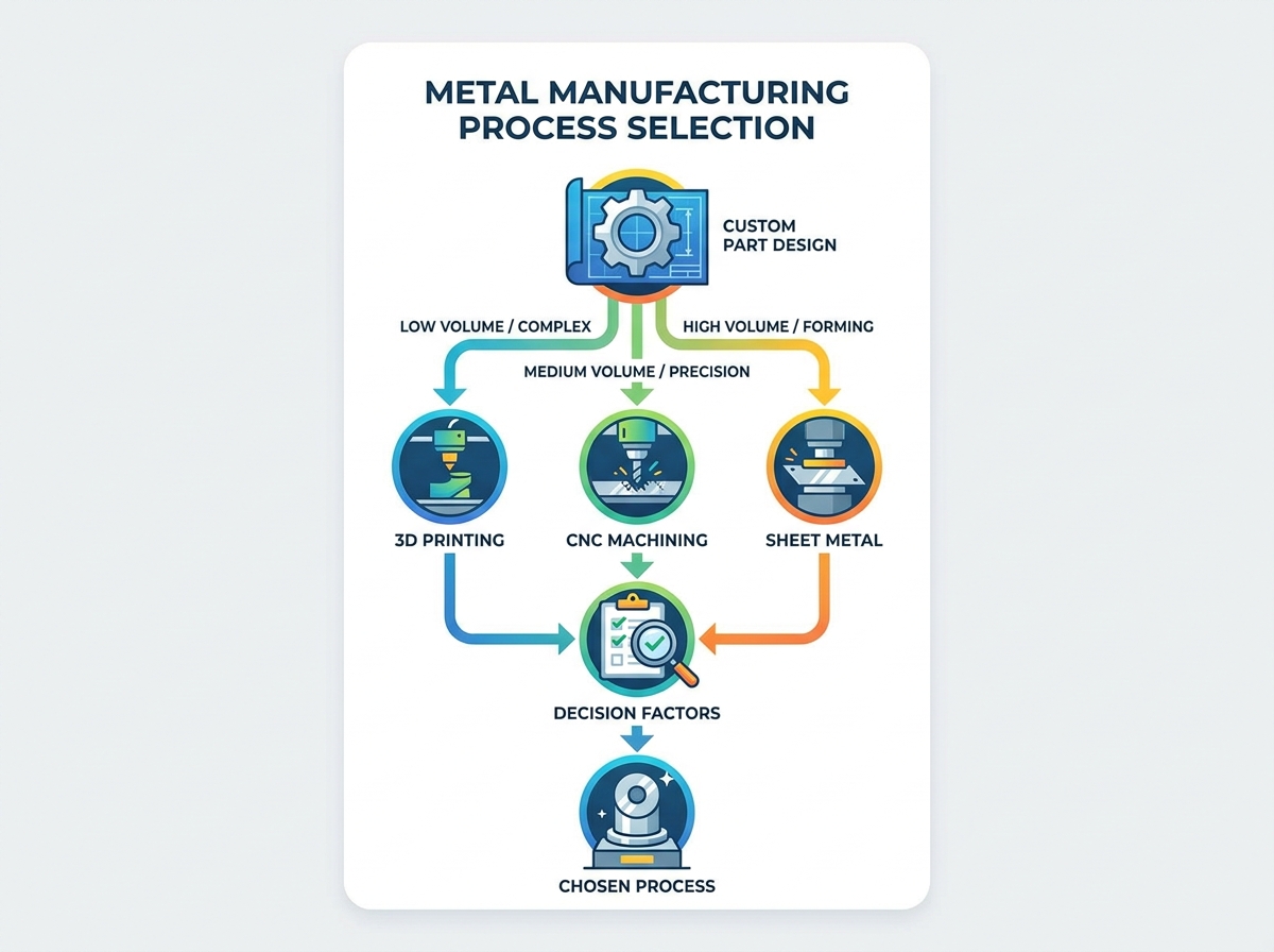
CNC machining removes material from a solid billet to achieve the final shape. This subtractive mechanism relies on rotating cutting tools or rotating workpieces. It is the best fit for applications requiring high precision, tight tolerances, and excellent surface finishes. CNC excels in low-to-medium production volumes where hard tooling is unjustified. However, it generates high material waste. The per-part production time is slower compared to stamping. Geometric limitations exist based on tool access and workholding requirements.
Modern 5-axis milling centers can reach nearly every side of a part in a single setup, reducing handling errors and improving positional accuracy. However, deep pockets with sharp internal corners remain impossible for round end mills. You must design with corner radii that match standard tool sizes. Turning centers with live tooling can mill features into cylindrical parts, combining two operations into one. Understanding the specific kinematics of the machine tools available will drastically improve your part designs.
Formative processes force molten metal or metal powder mixtures into a precision mold. These methods are the best fit for high-volume production runs requiring complex, net-shape parts with consistent repeatability. Once the mold is created, cycle times are incredibly fast. The primary limitation is the prohibitive upfront tooling cost. Mold creation involves long lead times and rigorous testing. Furthermore, casting is generally limited to specific alloys with lower melting points, such as zinc, aluminum, and magnesium.
Die casting requires strict adherence to design rules. You must include draft angles on vertical walls to allow the part to release from the steel die. Wall thicknesses must remain uniform to prevent sink marks and internal porosity as the metal cools and shrinks. Metal Injection Molding (MIM) allows for smaller, more complex steel parts but requires a debinding and sintering process that shrinks the part by up to 20%. You must account for this shrinkage in the initial mold design.
Sheet metal fabrication manipulates flat sheets of metal through laser cutting, press braking, and progressive dies. This category is the best fit for enclosures, brackets, chassis, and parts requiring a high strength-to-weight ratio. It offers rapid production for specific geometries. However, it is constrained to uniform wall thicknesses. It offers limited 3D geometric complexity compared to casting or machining. Engineers must adhere to specific design-for-bending rules, including minimum bend radii and strategic hole placement to prevent deformation.
When designing for sheet metal, you must calculate the K-factor to determine the flat pattern layout. Bending metal stretches the outside radius and compresses the inside radius. If you place a hole too close to a bend line, the press brake will distort the hole into an oval. Progressive stamping dies can punch, coin, and bend parts at hundreds of strokes per minute, but the tooling costs tens of thousands of dollars. Reserve stamping for massive production runs.
Metal 3D printing fuses metal powder layer by layer based on digital CAD data. This additive mechanism is the best fit for impossible geometries, such as conformal cooling channels or lightweight lattice structures. It enables zero-tooling rapid prototyping and complex part consolidation. The limitations include a high unit cost and slow production speeds. The "as-printed" surface finish is often rough, requiring secondary machining for mating surfaces. Build volumes are also restricted by the size of the printer chamber.
Direct Metal Laser Sintering (DMLS) creates fully dense parts by welding powder with a high-powered laser. The intense heat generates massive residual stresses, requiring heavy support structures to anchor the part to the build plate and prevent warping. You must design parts to be self-supporting wherever possible. Binder jetting is faster and cheaper but produces green parts that require furnace sintering, leading to shrinkage and lower final densities compared to DMLS.

Evaluating the right method requires a side-by-side comparison of capabilities. The table below synthesizes the primary characteristics of subtractive, formative, sheet metal, and additive methods. Use this data to eliminate unviable options early in the design phase.
Process Category | Setup Cost | Lead Time | Geometric Flexibility | Tolerance Range | Waste Factor |
|---|---|---|---|---|---|
CNC Machining | Low to Medium | Days to Weeks | Moderate | Excellent | High |
Die Casting / MIM | Very High | Weeks to Months | High | Good | Low |
Sheet Metal | Low to High | Days to Weeks | Low (2.5D) | Moderate | Moderate |
Metal 3D Printing | Low | Days | Very High | Moderate | Very Low |
This matrix highlights the inverse relationship between setup cost and per-part cost. High setup costs in casting yield low per-part costs at volume. Low setup costs in machining yield higher per-part costs. You must map your projected volume against these realities to find the break-even point.
Timeline trade-offs exist between zero-tooling and hard-tooling processes. Zero-tooling methods like 3D printing or basic CNC machining can deliver parts in days to weeks. They allow for rapid iteration and faster market entry. Hard-tooling processes like die casting or progressive stamping require weeks to months just to fabricate the molds or dies. You must align your project timeline with these realities. Committing to hard tooling too early locks in the design and delays initial physical testing.
Tooling modifications are expensive and slow. If you cut a steel mold for a die-cast part and realize you need to move a mounting boss by two millimeters, you might have to scrap the entire tool. Always validate your designs using a fast, zero-tooling Metal Manufacturing Process before issuing purchase orders for production tooling. Bridge tooling, using softer metals like aluminum for injection molds, can provide a middle ground for medium-volume runs.
Surface finish requirements drastically alter process selection. Compare the "as-cast" or "as-printed" surface roughness against an "as-machined" finish. Additive and formative methods often leave a textured surface that may not meet aesthetic or functional sealing requirements. To optimize budgets, specify tight tolerances only on critical mating surfaces. Applying universal tight tolerances across a non-critical part forces the manufacturer into slower, more expensive machining strategies when a faster method would suffice.
Surface roughness is measured in Ra (Roughness Average). A standard CNC milled finish might sit around 63 Ra, while a die-cast part might be 125 Ra. If you need an O-ring seal to hold pressure, you need a 32 Ra or better finish. This means you will have to machine the O-ring groove regardless of how the primary part was formed. Plan for these secondary operations when evaluating the total cycle time.
Understanding the cost structure prevents budget overruns. The formula includes setup and tooling costs, material costs, machine time, labor, and post-processing. A zero-tooling process has low setup costs but high machine time per part. A hard-tooling process has massive setup costs but pennies in machine time per part. Calculating the break-even point between CNC machining and die casting relies entirely on your projected volume over the product lifecycle.
Material yield also plays a massive role in unit economics. Machining a complex aerospace bracket out of a solid block of titanium might result in a 90% material waste factor. You are paying for expensive metal just to turn it into chips. In these scenarios, near-net-shape forging or metal 3D printing becomes economically viable simply by reducing the raw material input, even if the machine time is more expensive.

Optimizing for speed, cost, and quality simultaneously is a manufacturing myth. You must prioritize based on project constraints. Choosing rapid CNC machining for immediate speed sacrifices the low unit cost achievable through casting. Choosing stamping optimizes for high-volume cost but sacrifices upfront speed due to die creation. High quality and tight tolerances always increase both cost and time. Acknowledge these trade-offs early to set realistic expectations for your engineering and procurement teams.
If you demand a part in three days, the machine shop will interrupt other jobs, run overtime, and charge you a massive expedite fee. If you demand aerospace tolerances on a commercial budget, shops will simply no-quote the job. You have to understand what drives cost on the shop floor. Every tight corner radius, every deep hole, and every non-standard thread pitch adds setup time and tooling costs.
The chosen fabrication method forces specific design alterations. Designing for die casting requires adding draft angles to allow part ejection and maintaining uniform wall thickness to prevent sink marks. Designing for CNC machining requires avoiding deep, square internal pockets that round end mills cannot cut. Ignoring these constraints leads to the risk of over-engineering. Parts that could be simplified for cheaper fabrication end up costing exponentially more because the design fights the physics of the manufacturing equipment.
A good design works with the machine, not against it. If you are designing a milled part, make sure all features can be accessed from a single setup if possible. Every time the machinist has to unclamp the part, flip it, and re-indicate it, you lose accuracy and add labor cost. Standardize your hole sizes to match common drill bits. Avoid designing features that require custom-ground cutting tools.
Preparing CAD files correctly is critical for accurate quoting. Export models in standard formats like STEP or IGES. Accompany 3D models with detailed 2D technical drawings that specify Geometric Dimensioning and Tolerancing (GD&T) requirements. Utilize modern CAD tools and DFM plug-ins to identify manufacturing bottlenecks before requesting quotes. These tools highlight thin walls, inaccessible features, or missing draft angles, allowing you to correct the geometry before a machinist rejects the file.
Do not rely solely on the 3D model. The model tells the machine what shape to cut, but the 2D drawing tells the inspector what matters. If you do not specify a tolerance on a drawing, the shop will use their standard block tolerances, which might not meet your assembly requirements. Clearly call out threaded holes, surface finish requirements, and critical datums.
The sourcing landscape spans traditional machine shops and automated digital manufacturing networks. Traditional shops offer deep expertise but often have slower quoting cycles. Digital networks provide instant quoting algorithms based on uploaded geometry. Structure your Request for Quote (RFQ) meticulously to prevent delays. Include exact material grades, required quantities, surface finish specifications, and any necessary certifications. A vague RFQ guarantees back-and-forth negotiation and inaccurate initial pricing estimates.
Finalize the 3D CAD model and export it as a STEP file.
Create a 2D PDF drawing detailing all critical tolerances, threads, and finishes.
Compile a Bill of Materials (BOM) specifying exact alloy grades and required quantities.
Define all secondary operations, including heat treatment, plating, or anodizing.
Submit the complete package to multiple vendors to establish baseline market pricing.
Relying on a single vendor introduces operational risk. Address the risk of vendor lock-in, especially with proprietary tooling. Ensure you own the CAD data for your molds or dies. Evaluate a manufacturing partner’s machine park, production capacity, and quality management systems. Look for operational redundancy. If a vendor has only one specific 5-axis machine and it goes down, your production halts. Diversify your supply base for critical components to maintain uninterrupted assembly lines.
Audit your suppliers before awarding large contracts. Check their maintenance logs. A shop that does not calibrate its CNC machines will produce parts that drift out of tolerance over a long production run. Verify their material storage practices. If they mix up 6061 aluminum with 7075 aluminum, your parts will fail in the field. Trust, but verify through rigorous auditing.
Strict quality control is mandatory for structural or critical applications. Detail the necessity of material certifications and mill sheets to verify alloy composition. Mandate a First Article Inspection (FAI) report before authorizing full production runs. Ensure your vendor holds the necessary compliance standards for your sector, such as ISO 9001 for general manufacturing, AS9100 for aerospace, or specific medical-grade certifications. Skipping these verification steps invites liability and field failures.
Do not accept parts without documentation. A mill test report (MTR) proves that the raw material meets the chemical and mechanical properties specified on your drawing. An FAI report proves that the manufacturer's process can produce a part that meets every single dimension on the print. If a dimension is out of tolerance on the FAI, you must either reject the part or issue an engineering deviation before production continues.
The primary fabrication method rarely produces a finished, ready-to-install part. Identify the risks associated with multi-vendor supply chains when parts require secondary operations. Heat treatment, anodizing, plating, powder coating, or precision grinding add logistical complexity. Moving parts between different specialized facilities increases lead times, shipping costs, and the risk of damage. Partner with manufacturers who offer comprehensive in-house finishing services to streamline accountability and maintain strict quality oversight.
Every time a part changes hands, the risk of scrap increases. If a machine shop makes a perfect part, but the anodizer drops it or etches it too long, the part is ruined. You then have to figure out who pays for the scrapped material and the lost machining time. Consolidating operations under one roof eliminates this finger-pointing and ensures a single point of accountability for the final delivered component.
Run your CAD models through automated DFM software to eliminate impossible geometries before requesting quotes.
Order physical prototypes using a fast, zero-tooling method to validate form and fit before investing in hard tooling.
Audit your chosen manufacturing partner's quality control systems and demand First Article Inspection reports for all critical dimensions.
Consolidate secondary operations like heat treating and plating with your primary vendor to reduce logistical risks and scrap rates.
With extensive experience in precision manufacturing and custom metal fabrication, Emax has earned the trust of customers worldwide by delivering reliable, high-quality manufacturing solutions across a wide range of industries. Combining advanced CNC machining, sheet metal fabrication, metal casting, welding, and engineering expertise, the company helps customers efficiently transform product concepts into production-ready components while maintaining exceptional quality and cost efficiency.
From rapid prototyping and Design for Manufacturability (DFM) optimization to large-scale OEM production, Emax provides comprehensive engineering support, strict quality management, and dependable manufacturing services that enable customers to shorten development cycles, reduce production risks, and achieve long-term success in competitive global markets.
A: For low volumes, CNC machining and sheet metal fabrication are generally the most cost-effective. They require little to no upfront hard tooling, allowing you to pay primarily for material and machine time without amortizing expensive molds.
A: CNC machining offers superior surface finishes, tighter tolerances, and broader material options. Metal 3D printing excels at creating complex, impossible geometries like internal channels and lightweight lattices that CNC tools cannot reach.
A: The transition to stamping usually makes sense when production volumes reach the thousands or tens of thousands. At this scale, the high initial cost of creating progressive dies is offset by the drastically lower per-part production cost.
A: CNC machining routinely achieves tight tolerances of +/- 0.001 inches or better. Die casting typically yields broader tolerances around +/- 0.005 inches, often requiring secondary CNC machining on critical mating surfaces to achieve high precision.
A: Hard metals like titanium cause rapid tool wear in machining, sometimes making additive methods more attractive. Soft metals like aluminum are highly machinable. Alloys with specific melting points are required for successful die casting.
A: Export your 3D model as a STEP or IGES file. Always include a 2D PDF drawing detailing critical tolerances, threads, surface finishes, and material specifications. This eliminates ambiguity and ensures the manufacturer quotes exactly what you need.