


close
Choose Your Site
Global
Social Media


Views: 0 Author: Site Editor Publish Time: 2026-07-28 Origin: Site


Transitioning a finalized CAD design into physical mass production carries significant operational stakes. Late-stage manufacturing defects or supply chain bottlenecks can quickly derail product launches and damage brand reputation. Engineers and procurement teams face a complex challenge when moving from digital models to tangible components. You must select the right manufacturing process, balance initial tooling investments against per-unit production economics, and identify a manufacturing partner capable of maintaining strict tolerances at scale.
This guide serves as a comprehensive framework for evaluating manufacturing processes and implementing Design for Manufacturability (DFM). We will explore how to properly vet partners for the production of OEM Metal Parts. By understanding the intersection of material properties, production volumes, and quality control, you can streamline your transition from prototype to full-scale manufacturing.
Process Alignment: Selecting between CNC machining, sheet metal fabrication, or casting depends strictly on the intersection of volume projections, geometric complexity, and required tolerances.
DFM is Non-Negotiable: Engaging in Design for Manufacturability audits prior to mass production reduces material waste, minimizes secondary operations, and lowers piece-part costs.
Compliance and Traceability: Reliable production requires verifiable Quality Management Systems (QMS) and strict raw material traceability, especially in highly regulated industries.
Table of Contents
Defining the baseline tolerances required for your application is a primary step in production planning. Standard tolerances often sit around +/- 0.005 inches. High-precision applications may demand tight tolerances of +/- 0.001 inches or stricter. You must match the tolerance to the actual functional requirement of the component. Over-tolerancing drives up manufacturing resource requirements unnecessarily by forcing machinists to use specialized equipment and slower feed rates. Evaluate every dimension to ensure you only specify tight tolerances where mating parts or specific mechanical functions demand them.
On the shop floor, holding a +/- 0.001-inch tolerance requires rigid workholding, frequent tool changes, and temperature-controlled environments. If a bracket only holds a wire harness, a standard +/- 0.010-inch tolerance is perfectly acceptable. Engineers should apply Geometric Dimensioning and Tolerancing (GD&T) principles to define allowable variations in form and orientation, rather than just applying blanket linear tolerances across the entire drawing.
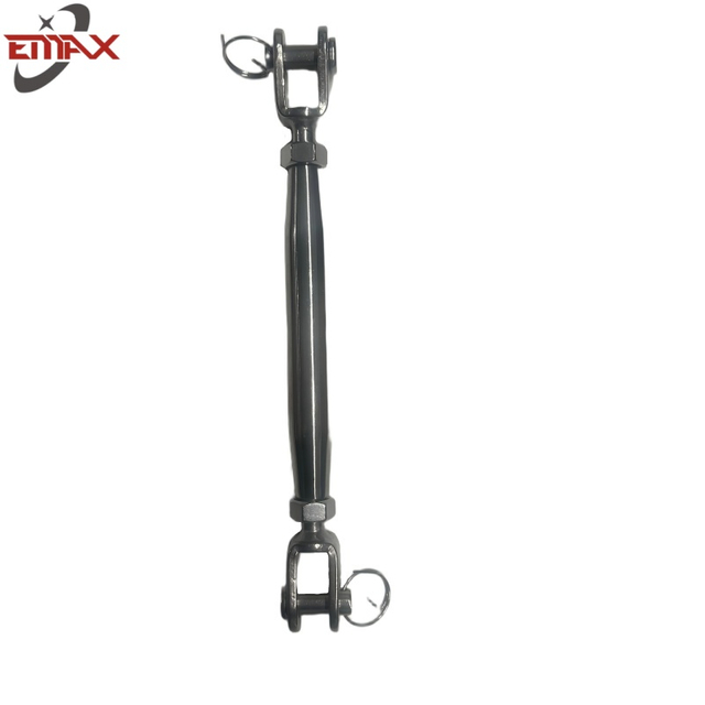
Production volume heavily dictates the most efficient manufacturing method. Low-volume, high-mix production generally favors CNC machining or sheet metal fabrication. These methods require minimal upfront tooling investments. Conversely, high-volume, low-mix production favors stamping or die casting. You must analyze the break-even points between these approaches. Short-run specialized machining makes sense for initial launches. Progressive die tooling investments become highly economical once production scales into the tens of thousands.
Consider the following volume thresholds when planning your production strategy:
Prototyping (1-50 units): Rely on 3-axis or 5-axis CNC machining and 3D printing. Focus is on speed and design validation.
Low Volume (50-500 units): CNC machining and basic sheet metal forming. Soft tooling may be introduced for simple bends.
Medium Volume (500-5,000 units): CNC turning centers with bar feeders, automated laser cutting, and robotic welding cells.
High Volume (5,000+ units): Die casting, investment casting, and progressive die stamping. Hard tooling is mandatory here.
The physical footprint and envelope size of a part directly dictate machine selection. Micro-machined internal components require Swiss-style lathes and specialized handling protocols. Massive structural welded assemblies demand large-format laser cutters, heavy-duty press brakes, and extensive floor space. You must evaluate whether a prospective partner has the specific equipment envelope to handle your dimensional scale efficiently.
For example, a Swiss lathe feeds bar stock through a guide bushing, providing extreme rigidity for long, slender parts like medical bone screws or aerospace pins. In contrast, a large structural frame for an industrial generator requires a 400-ton press brake and a gantry-style laser cutter. Matching your part's physical dimensions to the vendor's machine list prevents outsourcing delays and ensures the facility can physically maneuver your components through their quality control stations.
Operating environments dictate material selection. You must establish criteria based on required tensile strength, corrosion resistance, and thermal conductivity. Hard metals like stainless steel, titanium, and tool steel offer exceptional durability. They increase tool wear and require slower machining speeds. Soft metals like aluminum alloys, brass, and copper offer excellent machinability and formability. Comparing the mechanical properties against the manufacturing impact helps optimize both performance and production efficiency.
Material Category | Common Alloys | Machinability | Typical Applications |
|---|---|---|---|
Soft Metals | Aluminum 6061, Brass 360, Copper 110 | Excellent (High speeds, low tool wear) | Heatsinks, electrical contacts, lightweight enclosures |
Hard Metals | Stainless 316, Titanium Ti-6Al-4V, D2 Tool Steel | Poor to Fair (Requires rigid setups, coolant) | Medical implants, aerospace brackets, wear plates |
Carbon Steels | 1018, 1045, 4140 | Good (Predictable chip formation) | Shafts, gears, structural supports |
CNC machining excels at producing high precision, complex geometries for short-to-medium production runs. You must assess the necessity of 3-axis versus 5-axis machining based on part complexity. A 5-axis machine reduces setup times for multi-sided parts, improving overall accuracy by eliminating manual repositioning. Specialized short-run CNC setups are ideal for tight-tolerance OEM Metal Parts that require exact dimensional adherence without the wait for hard tooling.
Turning centers handle cylindrical components, while milling centers handle prismatic shapes. Modern mill-turn centers combine both capabilities, allowing raw bar stock to enter the machine and a completely finished, complex part to exit. This consolidation of operations drastically reduces handling time and minimizes the stack-up of tolerances that occurs when moving parts between different machines.

Sheet metal fabrication is best suited for enclosures, brackets, and large structural components. This process integrates laser cutting, punching, press brake forming, and automated welding. When designing for sheet metal, you must address specific needs such as bend allowances, relief cuts, and springback mitigation. Proper flat pattern development ensures the final folded geometry meets your exact specifications.
Engineers must account for the material's K-factor, which calculates the neutral axis shift during bending. Failing to calculate the K-factor correctly results in flanges that are either too long or too short after forming. Additionally, specifying standard bend radii that match the fabricator's existing press brake tooling prevents custom tooling delays and keeps the project on schedule.
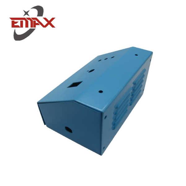
High-volume production often relies on metal casting and forging. These methods are ideal when tooling investments can be amortized over large runs. Investment casting provides high precision and complex internal shapes. Die casting offers rapid speeds for high-volume aluminum or zinc components. Forging delivers maximum structural integrity by aligning the grain structure of the metal. Choose the method that aligns with your mechanical requirements and production scale.
Forging is particularly valuable for components subjected to high impact or fatigue loading, such as automotive suspension arms or industrial crane hooks. The compressive forces used in forging eliminate internal voids and create a continuous grain flow that follows the contour of the part. Casting, while slightly less strong than forging, allows for intricate internal cavities that would be impossible to machine, such as engine block water jackets.
Industrial 3D printing is highly effective for rapid prototyping and creating complex internal geometries. It serves low-volume specialized components well. Additive manufacturing allows engineers to test physical iterations quickly. You must carefully plan the transition from additive prototypes to subtractive mass production. Features easily printed may require significant redesign to be milled or cast efficiently.
Direct Metal Laser Sintering (DMLS) fuses metal powder layer by layer, creating parts with mechanical properties rivaling billet material. While DMLS is excellent for conformal cooling channels in injection molds or lightweight aerospace lattices, it remains a slow process. When moving a 3D-printed prototype to CNC machining for mass production, you must eliminate internal undercuts and ensure all features are accessible by standard cutting tools.
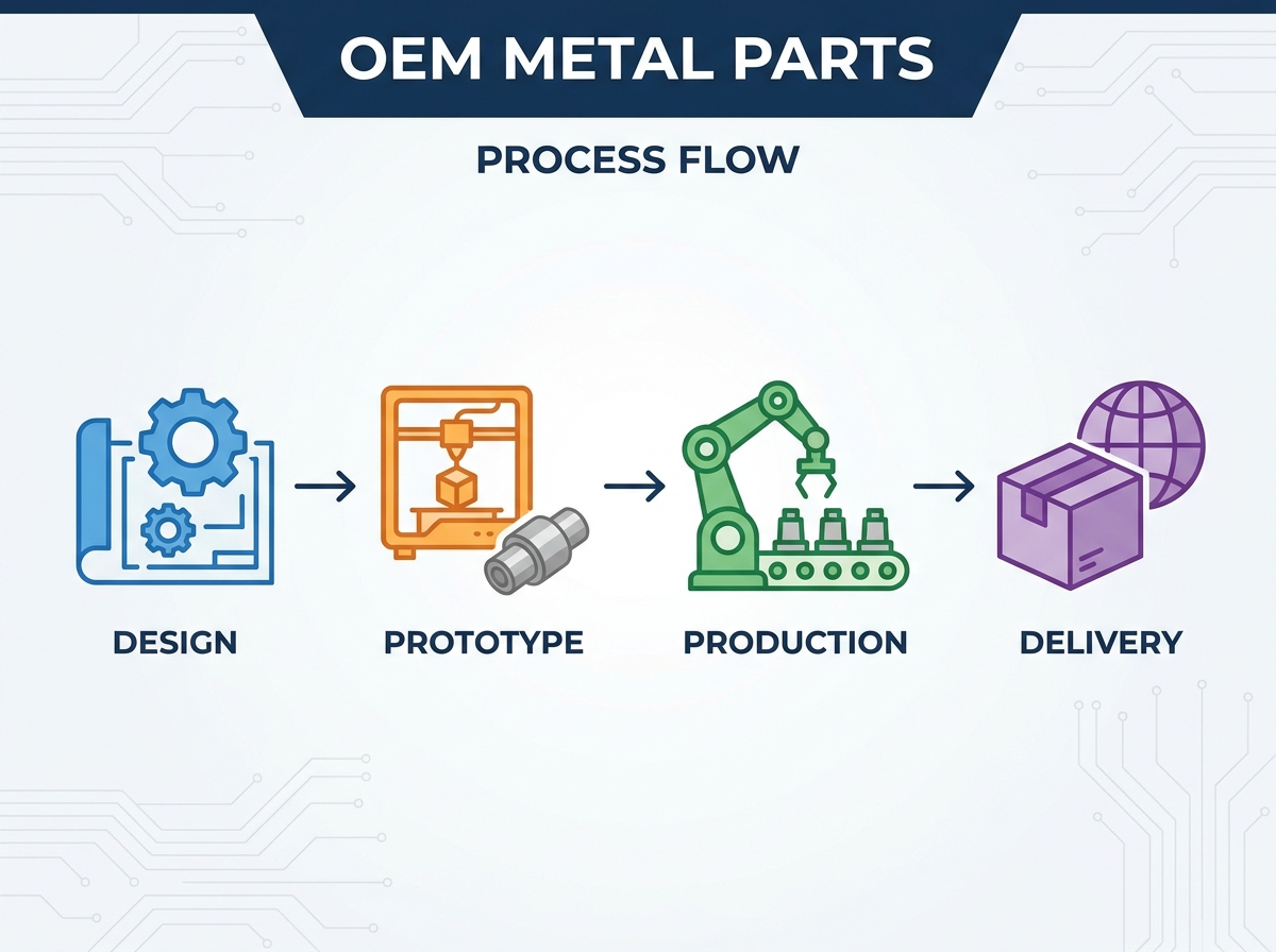
Partner-led design assistance provides immense value during early development. Experienced engineers help translate raw conceptual drawings into production-ready CAD files. Establishing protocols for aligning custom client specifications with a manufacturer’s in-house equipment limits prevents downstream delays. Collaborative co-engineering ensures your design is actually manufacturable before a single piece of metal is cut.
A practical co-engineering session often involves reviewing the CAD model layer by layer. The manufacturing partner will point out areas where a standard end mill cannot reach or where a sheet metal bend is too close to a hole, causing distortion. By adjusting these features early, you avoid the scenario where a machinist has to stop production to request a design deviation.
Common design flaws easily inflate production resources. Deep pockets, non-standard hole sizes, and sharp internal corners require specialized tooling and extended machining time. A thorough DFM review identifies these drivers early. By standardizing radii, utilizing common tap sizes, and minimizing setups, you significantly streamline the manufacturing process.
Sharp Internal Corners: End mills are round. Machining a perfectly square internal corner requires slow, expensive electrical discharge machining (EDM). Add a radius to internal corners to allow standard end mills to clear the pocket.
Deep Pockets: Pockets deeper than four times the tool diameter cause tool deflection and chatter. Redesign to reduce depth or allow for larger corner radii so thicker, more rigid tools can be used.
Non-Standard Threads: Specifying a custom thread pitch forces the shop to buy custom taps or thread mill the feature slowly. Stick to standard UNC or UNF thread profiles.
Efficient material usage directly impacts production economics. In sheet metal fabrication, advanced nesting software arranges flat patterns to minimize scrap. In CNC machining, optimizing the initial stock size reduces raw material waste and decreases the time spent milling away excess metal. Smart material yield optimization is a hallmark of an experienced manufacturing partner.
For example, if a part is designed to be 2.1 inches wide, the shop must purchase 2.5-inch bar stock and mill away 0.4 inches of material. If the design can be slightly modified to a 1.9-inch width, the shop can use standard 2.0-inch bar stock, drastically reducing both material waste and machining time. These small adjustments compound significantly over a run of ten thousand parts.
Never commit to expensive hard tooling without physical validation. Short-run prototypes allow you to test form, fit, and function in real-world conditions. This validation phase highlights unforeseen assembly issues or dimensional interferences. Refining the design during the prototype stage prevents catastrophic modifications to hardened steel molds or progressive dies later.
A standard validation protocol includes producing a small batch of 10 to 50 units using soft tooling or CNC machining. These units are then assembled into the final product and subjected to functional testing. Any interferences, such as a bracket rubbing against a wiring harness, are documented. The CAD model is updated, and only then is the green light given to cut the hardened steel production tooling.

Verifiable Quality Management Systems are baseline indicators of process control. Certifications like ISO 9001 demonstrate a commitment to general manufacturing consistency. Specialized industries require stricter standards, such as AS9100 for aerospace or ISO 13485 for medical devices. A robust QMS ensures that every batch meets the same rigorous standards as the approved first article.
When auditing a potential partner, look beyond the certificate on the wall. Ask to see their corrective and preventive action (CAPA) logs. A healthy QMS actively identifies non-conformances and implements permanent root-cause fixes. Review their calibration schedules for inspection equipment like micrometers and Coordinate Measuring Machines (CMMs) to ensure their measurements are actually accurate.
Fragmented supply chains introduce significant risks regarding lead times and quality control. Partners offering in-house finishing services reduce these risks. Capabilities like anodizing, powder coating, plating, and sub-assembly keep the project under one roof. This consolidation reduces transit times, lowers shipping logistics, and eliminates quality disputes between multiple vendors.
If a machined part is sent to an external vendor for anodizing and returns with dimensional issues due to excessive coating thickness, the machine shop will blame the plater, and the plater will blame the machine shop. An integrated manufacturer takes full responsibility for the final delivered component, managing the masking and coating allowances internally to guarantee the final dimensions meet the print.
Strict raw material traceability is vital, especially in highly regulated sectors. Assess a manufacturer's ability to provide accurate material test reports (MTRs) for every batch. Evaluate their supply chain resilience. A reliable partner navigates raw material shortages through diversified sourcing and strategic inventory management, ensuring your production lines never stall.
Traceability means that if a component fails in the field five years from now, you can trace that specific serial number back to the exact heat lot of steel poured at the mill. The manufacturer must maintain digital records linking the MTRs to the specific work orders and shipping documents. This level of documentation is non-negotiable for aerospace, medical, and automotive applications.
Manufacturing always involves balancing upfront capital expenditure against ongoing unit economics. You need a clear framework for calculating the return on investment for hard tooling. Stamping dies require significant initial capital but yield an incredibly low per-unit resource requirement. Tool-less processes like laser cutting have zero tooling expenditure but maintain a higher per-unit rate. Analyze your estimated annual usage to find the optimal crossover point.
To calculate the crossover point, plot the total production expenditure of both methods on a graph. The X-axis represents the number of units, and the Y-axis represents total capital deployed. The point where the two lines intersect is your break-even volume. If your projected life-cycle volume exceeds this number, invest in the hard tooling. If it falls short, stick with the tool-less CNC or laser cutting processes.
Mapping out realistic timelines prevents launch delays. Custom metal components require sequential phases. You must account for DFM review, first article inspection (FAI), tooling fabrication, and full-scale production runs. Rushing these steps often results in compromised quality. Build buffer time into your schedule to accommodate tooling adjustments and material procurement.
DFM and Engineering Review: 1 to 2 weeks.
Material Procurement: 1 to 4 weeks, depending on alloy availability.
Tooling Fabrication (if applicable): 4 to 12 weeks for complex dies or molds.
First Article Inspection (FAI): 1 to 2 weeks for production, measurement, and approval.
Full-Scale Production: 2 to 6 weeks, depending on volume and secondary operations.
Protecting proprietary CAD files is critical when sharing designs with external fabrication facilities. Implement strict Non-Disclosure Agreements (NDAs) before transmitting any data. Utilize secure file transfer protocols and limit access to sensitive intellectual property. Ensure your manufacturing partner has robust digital security measures to prevent unauthorized distribution of your designs.
On a practical level, only share the specific models and drawings necessary for quoting. If you are sourcing a single bracket, do not send the entire top-level assembly model of your product. Strip out internal components and proprietary mechanisms from the CAD files before exporting the STEP files for the vendor.
Continuous revisions delay the transition to mass production. Feature creep occurs when teams constantly add new requirements during the prototyping phase. You must lock in design specifications at a defined milestone. Establish a strict change-order process to evaluate the impact of any late-stage modifications on tooling and delivery schedules.
Once the First Article is approved, implement a design freeze. Any subsequent changes must go through an Engineering Change Order (ECO) board. The board evaluates how moving a hole by 0.1 inches will impact the existing stamping die, the assembly fixtures, and the automated inspection routines. If the change does not provide a massive functional benefit, it is rejected to keep production on schedule.
Quality fade happens when standards slowly slip over long production runs. Establish protocols for ongoing statistical process control (SPC) to monitor critical dimensions. Routine tooling maintenance is essential to prevent wear from affecting part geometry. Rigorous inspection schedules ensure the ten-thousandth part matches the approved First Article perfectly.
Implement a sampling plan based on Acceptable Quality Limit (AQL) standards. Instead of just checking the first and last part of a shift, operators should pull parts at defined intervals and plot the dimensions on a control chart. If the dimensions start trending toward the upper or lower tolerance limit, the operator stops the machine and changes the cutting insert before a bad part is ever produced.
Compile a comprehensive Request for Quote (RFQ) package containing finalized 3D STEP files and fully dimensioned 2D PDF drawings.
Define your Estimated Annual Usage (EAU) and typical release quantities to allow vendors to quote the most efficient manufacturing process.
Initiate a formal Design for Manufacturability (DFM) review with your shortlisted vendors to identify and eliminate cost drivers before cutting metal.
Request and review sample material test reports (MTRs) and First Article Inspection (FAI) documentation to verify the vendor's quality control capabilities.
With extensive experience supporting global OEM manufacturing projects, Emax has become a trusted manufacturing partner for customers seeking high-quality custom metal parts and precision-engineered components. By integrating advanced CNC machining, sheet metal fabrication, metal casting, welding, and rigorous quality management, the company helps transform product concepts into reliable, production-ready solutions with consistent quality and manufacturing efficiency.
From rapid prototyping and Design for Manufacturability (DFM) optimization to large-scale production, Emax provides comprehensive engineering support, dependable supply chain management, and customized manufacturing services that help customers accelerate product launches, reduce production risks, and achieve long-term business success.
A: OEM components are manufactured specifically for the original equipment manufacturer's final product. They adhere to exact original specifications and tolerances. Aftermarket parts are produced by third parties as replacements or upgrades, often varying slightly from the original design parameters to reduce manufacturing complexity.
A: Low volumes favor processes with low setup and zero tooling requirements, such as CNC machining or laser cutting. High volumes justify the significant initial tooling investments required for stamping or die casting, as these methods drastically reduce the per-unit resource requirement at scale.
A: DFM ensures a product is designed specifically to be easily and efficiently manufactured. It identifies complex features, reduces material waste, and minimizes the need for secondary operations, ultimately lowering production resources and shortening lead times.
A: Material selection impacts both the part's functional performance and its manufacturability. Hard metals offer durability but slow down machining and increase tool wear. Soft metals are easier to form and machine but may lack the necessary tensile strength for heavy-duty structural applications.
A: MTRs verify the chemical composition and mechanical properties of the raw material used in production. They provide essential traceability and ensure compliance with industry standards, which is critical for applications in aerospace, medical, and automotive sectors where material failure is catastrophic.