


close
Choose Your Site
Global
Social Media


Views: 0 Author: Site Editor Publish Time: 2026-07-28 Origin: Site


Industrial manufacturing demands absolute precision. Minor deviations in tolerances or poor material selection lead to catastrophic assembly failures, delayed production timelines, and significant budget overruns. Moving from a CAD design to physical production requires balancing structural integrity, cost-efficiency, and scalability while navigating complex fabrication techniques. Engineering teams often struggle to translate digital models into physical parts without encountering unforeseen manufacturing constraints. This guide serves as a technical roadmap for engineering and procurement teams. You will learn how to evaluate fabrication processes, optimize designs for manufacturability, and vet potential manufacturing partners to ensure project success. We focus on practical, field-tested strategies to bridge the gap between digital models and physical reality, ensuring your components meet strict performance standards.
Design for Manufacturability (DFM) is paramount: Early alignment on bend radii, hole placement, and standard tolerances prevents costly rework and material waste.
Process selection dictates project viability: The choice between laser cutting, waterjet, or stamping must align directly with volume requirements, material thickness, and edge-quality standards.
Material and finish pairing determines lifecycle ROI: Selecting the right alloy (e.g., 304 vs. 316 stainless steel) and finishing method is critical for environmental compliance and long-term durability.
Partner capabilities mitigate supply chain risk: A qualified fabrication partner must demonstrate verifiable quality control (e.g., ISO 9001), automated equipment capacity, and transparent lead-time management.
Table of Contents
The physical transformation of raw flat stock into a finished component follows a strict, highly controlled sequence. Understanding this workflow helps engineers anticipate where defects might occur and how to design around them. The process of Sheet Metal Fabrication generally moves through the following stages:
Material Preparation: Raw flat stock arrives as large coils or standard-sized sheets. Operators inspect the material for surface defects and verify gauge thickness before loading it onto the cutting bed.
Cutting and Blanking: Lasers, waterjets, or plasma cutters slice the 2D flat pattern out of the raw sheet. This step defines the outer perimeter and internal cutouts.
Forming and Bending: Press brakes or stamping dies apply targeted force to bend the flat blank into a 3D geometry. This requires calculating bend allowances to account for material stretching.
Joining and Assembly: Individual formed parts are welded, riveted, or fastened together to create complex sub-assemblies.
Surface Finishing: The assembled component undergoes grinding, deburring, and chemical treatments like powder coating or anodizing to protect against corrosion.
Quality Verification: Inspectors use coordinate measuring machines (CMM) and optical scanners to verify that the final part matches the original CAD model within specified tolerances.
Working with sheet metal requires a deep understanding of material physics. Engineers must account for yield strength, which dictates how much force is needed to permanently deform the metal. Tensile strength determines the maximum stress the material can withstand before tearing. Material memory, or springback, forces fabricators to over-bend parts slightly so they relax into the correct final angle.
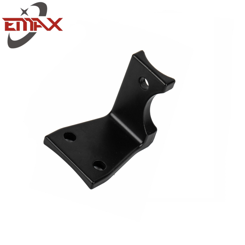
Custom fabrication serves critical roles across multiple heavy-duty sectors. The versatility of sheet metal allows it to be adapted for both structural load-bearing applications and protective enclosures.
Industry Sector | Typical Applications | Key Engineering Requirements |
|---|---|---|
Heavy Machinery | Equipment chassis, operator cabs, structural brackets | High tensile strength, vibration resistance, heavy-gauge forming |
Aerospace | Interior bulkheads, seating frames, avionics enclosures | Extreme weight reduction, tight tolerances, AS9100 compliance |
Electrical & Power | NEMA-rated enclosures, busbars, switchgear cabinets | Environmental sealing, thermal management, electrical conductivity |
Medical Devices | Diagnostic equipment chassis, surgical carts, fluid housings | Hygienic surfaces, corrosion resistance, ISO 13485 compliance |
Establishing baseline expectations for tolerances is vital before cutting any material. Standard industrial applications often follow ISO 2768-m guidelines, which provide a reliable baseline for general fabrication. However, aerospace components or precision medical devices require much tighter controls, often demanding tolerances within +/- 0.005 inches.
Tolerance stacking presents a significant challenge in complex multi-part assemblies. When multiple folded parts are bolted or welded together, the minor deviations from each individual bend accumulate. If a chassis consists of five interconnected brackets, and each bracket is off by 0.010 inches, the final assembly could be misaligned by 0.050 inches. This misalignment compromises structural integrity, forces manual rework on the assembly line, and introduces stress concentrations that can lead to premature mechanical failure.
The cost-to-volume ratio dictates the most appropriate fabrication method. Engineers must evaluate the breakeven point where transitioning from manual processes to automated production makes financial sense.
CNC press braking is ideal for low-volume prototyping and short production runs. It offers immense flexibility because operators can change tooling quickly without high upfront costs. You can bend a dozen different geometries in a single shift. Conversely, hard tooling and stamping require significant upfront investment to machine custom steel dies. However, once the die is created, the per-part production time drops to seconds. Identifying the exact volume threshold where custom hard tooling becomes viable ensures long-term production efficiency.
Selecting the right cutting technology depends entirely on material thickness, required edge quality, and thermal sensitivity. Fiber laser cutting provides high-speed, high-precision processing for thin to medium-gauge metals. Lasers excel at cutting intricate geometries and small holes with minimal kerf width. They are the industry standard for carbon steel up to 3/4 inch and stainless steel up to 1/2 inch.
Plasma cutting serves as the workhorse for thick, heavy plates where edge precision is secondary to raw cutting speed. It uses an accelerated jet of hot plasma to melt through thick structural steel. While faster and cheaper for heavy gauges, plasma leaves a rougher edge and a wider kerf.
Waterjet cutting is essential for heat-sensitive materials. By using a high-pressure stream of water mixed with abrasive garnet, waterjets cut through metal without generating heat. This prevents Heat-Affected Zones (HAZ), which can alter the metallurgical properties of the metal and cause structural material warping. Waterjet is ideal for thick aluminum, titanium, and complex aerospace alloys.
CNC press braking utilizes multi-axis back-gauging to accommodate variable geometries. The back-gauge acts as a robotic stop that positions the flat sheet precisely over the lower die. As the upper punch descends, it forces the metal into the die to create the bend. Modern CNC brakes automatically adjust for material thickness variations and calculate the exact tonnage required.
Stamping and punching rely on turret punch presses to create rapid, repeatable features. A turret press houses dozens of different punch-and-die combinations in a rotating carousel. It can punch holes, create louvers, and stamp extrusions in rapid succession, making it highly efficient for perforated panels or complex electronic enclosures.
Roll forming is preferred for producing continuous, long-profile industrial components. The flat sheet passes through a series of mated roller dies, each making an incremental bend until the final cross-section is achieved. This process is highly efficient for producing structural channels, roofing panels, and custom tracks.

Joining sheet metal requires balancing structural strength with aesthetic requirements. TIG (Tungsten Inert Gas) welding offers precise control over heat input, making it ideal for thin materials and visible seams where aesthetics matter. MIG (Metal Inert Gas) welding is faster and better suited for thicker structural components where deep penetration is required.
Cold-joining techniques are necessary when joining dissimilar metals or pre-coated sheets that cannot withstand welding heat. Rivets, engineered structural adhesives, and toxing (a mechanical clinching process) provide strong bonds without thermal distortion.
Self-clinching fasteners, such as PEM nuts, studs, and standoffs, are pressed directly into pre-punched holes. The metal cold-flows into the fastener's annular groove, locking it permanently in place. Combined with mechanical interlocks like tab-and-slot designs, these fasteners drastically reduce manual assembly time and ensure perfect alignment without complex welding fixtures.
Carbon steel offers high tensile strength and excellent formability, making it the default choice for heavy structural applications, machinery frames, and industrial brackets. However, it requires secondary surface treatments like powder coating or galvanizing to prevent rust.
Stainless steel provides inherent corrosion resistance due to its chromium content. Grade 304 is the standard for general industrial use, while Grade 316 contains molybdenum for superior resistance to chlorides and harsh chemicals. Stainless steel is mandatory for food-grade processing equipment, medical devices, and marine environments where hygiene and longevity are non-negotiable.
Aluminum delivers significant strength-to-weight advantages, making it indispensable for aerospace, automotive, and outdoor enclosures. It naturally forms a protective oxide layer, offering excellent corrosion resistance.
Alloy 5052 is highly formable and easily welded, making it the go-to choice for complex bent enclosures. Alloy 6061 offers higher structural strength but is prone to cracking during tight-radius bends. Engineers must account for aluminum's specific formability limits and higher springback characteristics compared to steel.
Copper and brass are specified for industrial use cases requiring high electrical or thermal conductivity. Copper is the standard for power distribution blocks, electrical busbars, and grounding straps. Brass offers excellent machinability and corrosion resistance, often used in specialized electrical enclosures, marine hardware, and decorative architectural elements.
Standard engineering rules dictate minimum bend radii relative to material thickness (t) to prevent cracking on the outside of the bend. For example, aluminum 6061-T6 typically requires a minimum bend radius of 3t to 6t, while softer mild steel can often be bent at 1t.
Hole placement is equally critical. A general rule of thumb requires the distance from the edge of a hole to the start of a bend to be at least 1.5 times the material thickness plus the bend radius. Placing holes too close to the bend line causes the hole to stretch, deform, and distort as the material pulls during the forming process.
Bend reliefs are necessary when a bend does not run the entire length of a part. Without a relief cut, the material will tear at the transition point between the bent flange and the flat surface. The width of the bend relief should be at least equal to the material thickness, and the depth should extend past the bend radius.
Calculating minimum flange widths based on sheet thickness and die selection prevents the material from slipping into the V-die during forming. If a flange is too short, it cannot span the width of the lower die, making it impossible to bend accurately using standard air bending techniques.
Springback occurs when material attempts to return to its original flat shape after the bending force is removed. CNC fabricators compensate by over-bending the part. The exact amount of over-bend depends on the material's yield strength, thickness, and grain direction. Bending across the material grain reduces springback and the risk of cracking compared to bending parallel to the grain.
Design strategies must also minimize thermal warpage during high-heat processes. When welding long seams or laser cutting intricate patterns, the localized heat causes the metal to expand and contract unevenly. Engineers mitigate this by designing intermittent stitch welds instead of continuous seams and incorporating stiffening ribs into large flat panels.
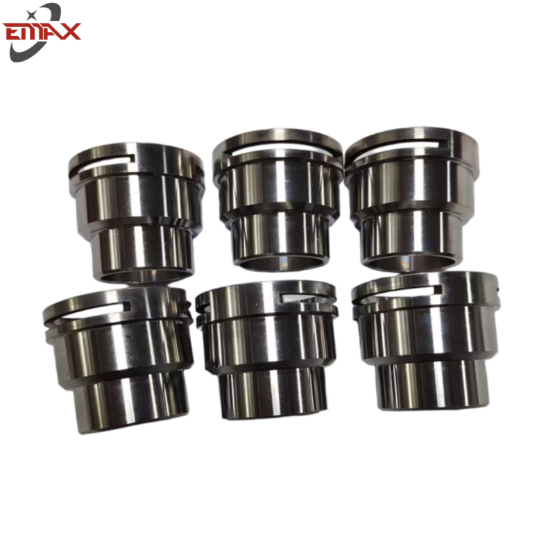
Surface finishing protects the raw metal from environmental degradation and provides the final aesthetic appearance. Powder coating applies a dry thermoplastic powder that is baked in an oven, creating a durable, impact-resistant, and chemically resistant finish superior to standard wet paint.
Anodizing is an electrochemical process specifically for aluminum. It thickens the natural oxide layer, increasing surface hardness, wear resistance, and corrosion protection without adding significant dimensional thickness. This makes it ideal for precision parts where paint thickness would interfere with assembly tolerances.
Zinc plating, chromate conversion, and hot-dip galvanizing offer heavy-duty environmental protection for carbon steel components exposed to harsh outdoor conditions.
Surface treatments must comply with strict environmental regulations, including RoHS (Restriction of Hazardous Substances) and REACH. Engineers must specify hexavalent chromium-free conversion coatings and lead-free plating processes. Understanding the regulatory impact of specific chemical treatments ensures long-term compliance and prevents costly redesigns for products entering the European market.
Evaluating a partner’s investment in automation is critical for ensuring consistency and reducing lead times. Automated material handling systems, such as tower loading systems, allow lasers to run unattended overnight. Robotic welding cells provide perfectly consistent weld seams for high-volume production runs.
When auditing a facility, look for standard industrial machinery: high-wattage fiber lasers, multi-tool CNC turret punches, automated press brakes with active angle measurement, and Coordinate Measuring Machines (CMM) for precise quality verification.
Non-negotiable certifications prove a fabricator's commitment to process control. ISO 9001:2015 serves as the baseline for general manufacturing. Aerospace projects require AS9100 certification, medical devices demand ISO 13485, and defense contracts necessitate ITAR registration.
A qualified partner must provide comprehensive documentation. First Article Inspection (FAI) reports verify that the initial production run meets all CAD specifications. Production Part Approval Process (PPAP) documentation ensures the manufacturing process is stable and repeatable.
A fabricator's internal supply chain directly impacts your project timeline. Evaluate their raw material sourcing networks and direct mill relationships. Fabricators who stock common gauges of steel and aluminum internally can buffer against sudden market shocks and material shortages, ensuring reliable delivery schedules even during supply chain disruptions.
Successful sheet metal fabrication depends on selecting the right materials, manufacturing processes, and production partners from the earliest design stage. Applying Design for Manufacturability (DFM) principles and choosing experienced fabrication specialists can significantly improve product quality, reduce production costs, and shorten lead times.
About Emax
Emax is a professional custom metal fabrication manufacturer specializing in sheet metal fabrication, CNC machining, metal stamping, welding, and complete OEM manufacturing solutions. With advanced production equipment, strict quality control systems, and extensive manufacturing experience, Emax delivers high-precision metal components for customers across a wide range of industrial sectors.
Select materials based on strength, corrosion resistance, manufacturability, and application requirements.
Optimize your design using DFM principles before production begins.
Choose the most suitable cutting, forming, and finishing processes for your project.
Verify your supplier's manufacturing capabilities, certifications, and quality management system.
Before selecting a sheet metal fabrication partner, carefully evaluate their engineering expertise, production capacity, quality assurance processes, and project management capabilities to ensure consistent product quality and reliable delivery.
A: Typical industry standards range from +/- 0.005 to +/- 0.015 inches. The exact tolerance depends heavily on the specific fabrication process, the material thickness, and the geometric complexity of the final part.
A: Thicker materials require significantly higher tonnage press brakes for forming. They also dictate cutting methods, often requiring plasma cutting over laser cutting, and severely limit the ability to achieve tight bend radii without cracking.
A: Plasma cutting offers the best cost and speed advantages for thick structural steel. However, if edge quality is critical and heat-affected zones must be avoided, waterjet cutting is the superior, albeit slower, alternative.
A: Standardize hole sizes to reduce tool changes. Use common material gauges that fabricators keep in stock. Loosen non-critical tolerances, design for self-clinching hardware instead of custom welding, and utilize tab-and-slot alignments to speed up assembly.
A: ISO 9001 is the absolute baseline for quality management. Depending on your industry, look for specialized certifications including AWS certified welders, AS9100 for aerospace components, or ITAR registration for defense applications.
A: Realistic timeframes for prototypes typically range from 1 to 3 weeks. Factors that accelerate or delay this include raw material availability, the complexity of custom tooling required, and specialized post-processing finishing requirements.